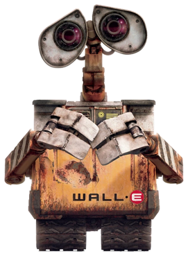
Overview
This page will explain the sensors and peripherals of the WALL-E project, and the brainstorming involved to the design choices and objectives of WALL-E
Components List
- Romi Pololu Motors w/ Encoder x2
- BNO055 IMU
- HCSR04 Ultrasonic Sensor
- OV2640 ArduCam Camera
- MG90s Servos x4
Component Description and Use
- Romi Pololu Motors: With have experience working with these motors with a previous differential drive robot, we felt comfortable creating motor drivers for these motors in C++ and followed similar PCB design aspects in order to achieve their full use.
- BNO055 IMU: The IMU portion was also decided on due to having prior experience with the IMU as well as for the purpose of using the yaw/heading data for positional corrections and turning corrections for our PIDController.
- HCSR04 Ultrasonic Sensor: This device was also selected for detecting objects at a certain range using the device as a threshold marker for speed and motor control when approaching an object.
- OV2640 ArduCam Camera: This aspect of our design choice was made in order to give WALL-E more of a challenge and different aspect. The use of the camera was to be used for basic object detection or specific color detection, without the use of heavy API such as OpenCV.
- MG90s Servos: The servos were a design choice that was adapted from the original designer of the WALL-E CAD model. The purpose of these servos would be to move the arms and hands in order to create the holding and lifting aspect of WALL-E.
Peripheral and Sensor Locations
WALL-E Component Housing Area
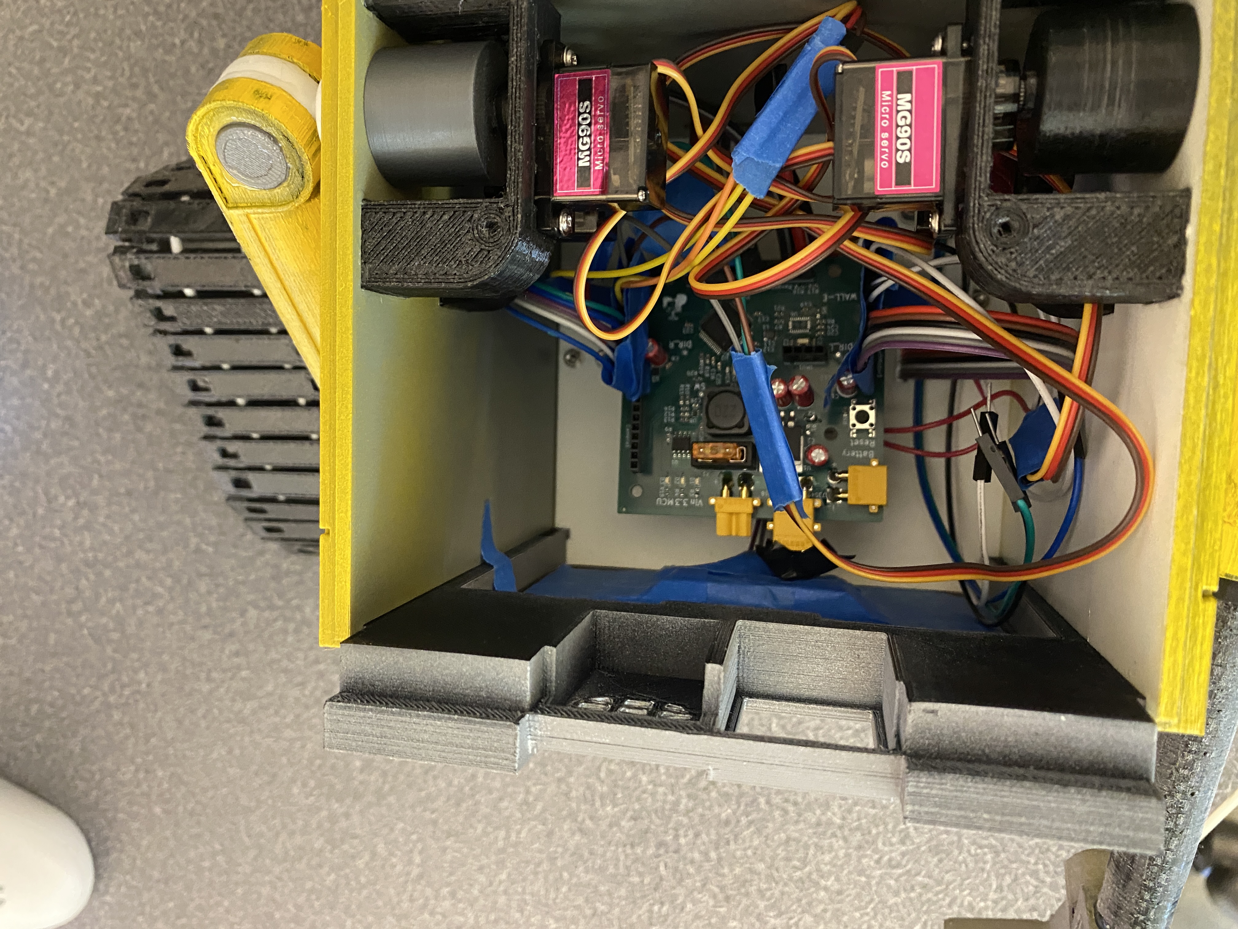
WALL-E HOUSING
Camera
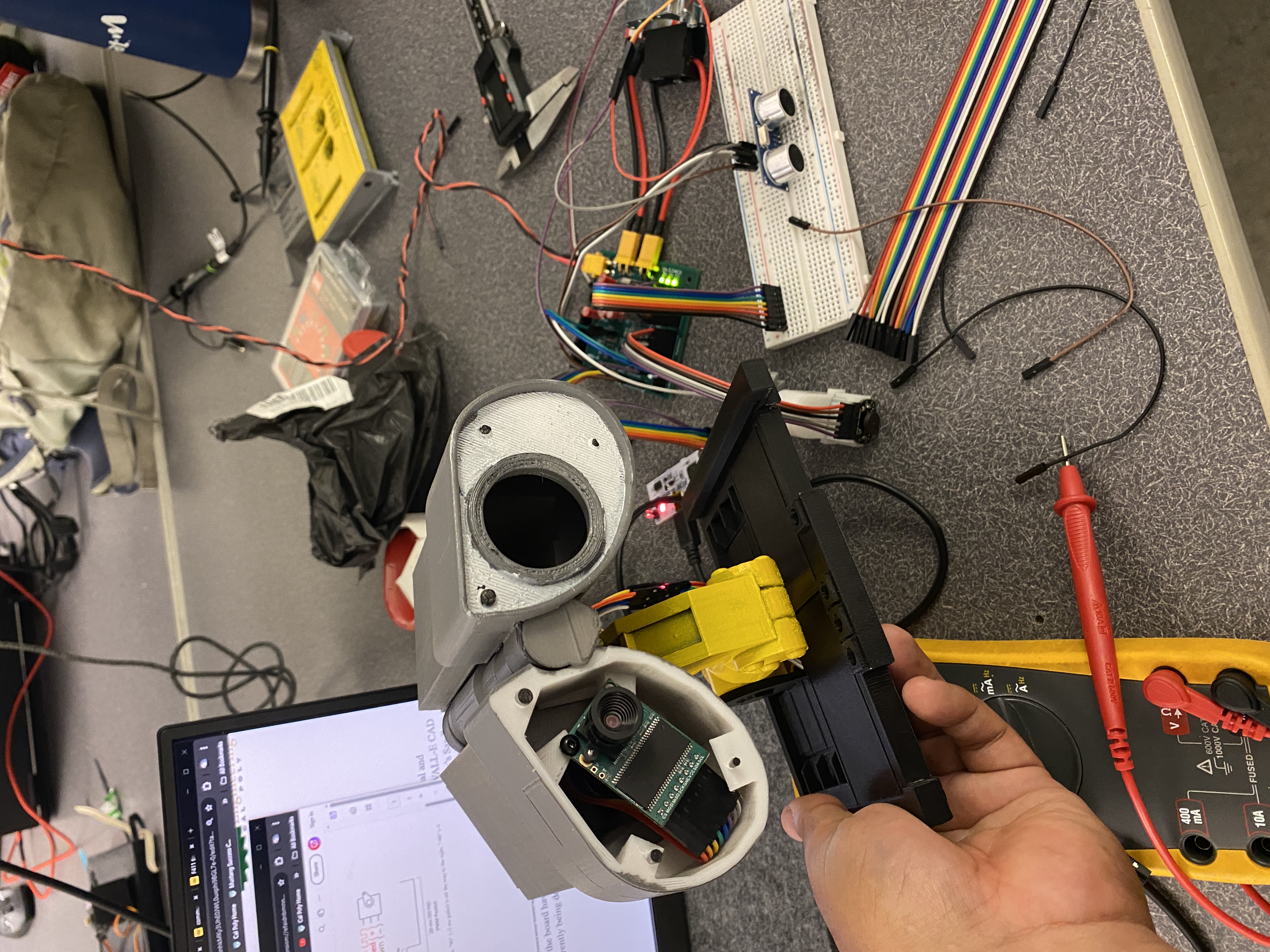
WALL-E Camera Placement
- Camera is located in the WALL-E eye socket. To learn more about the design visit the Mechanical Design page.
Ultrasonic Sensor
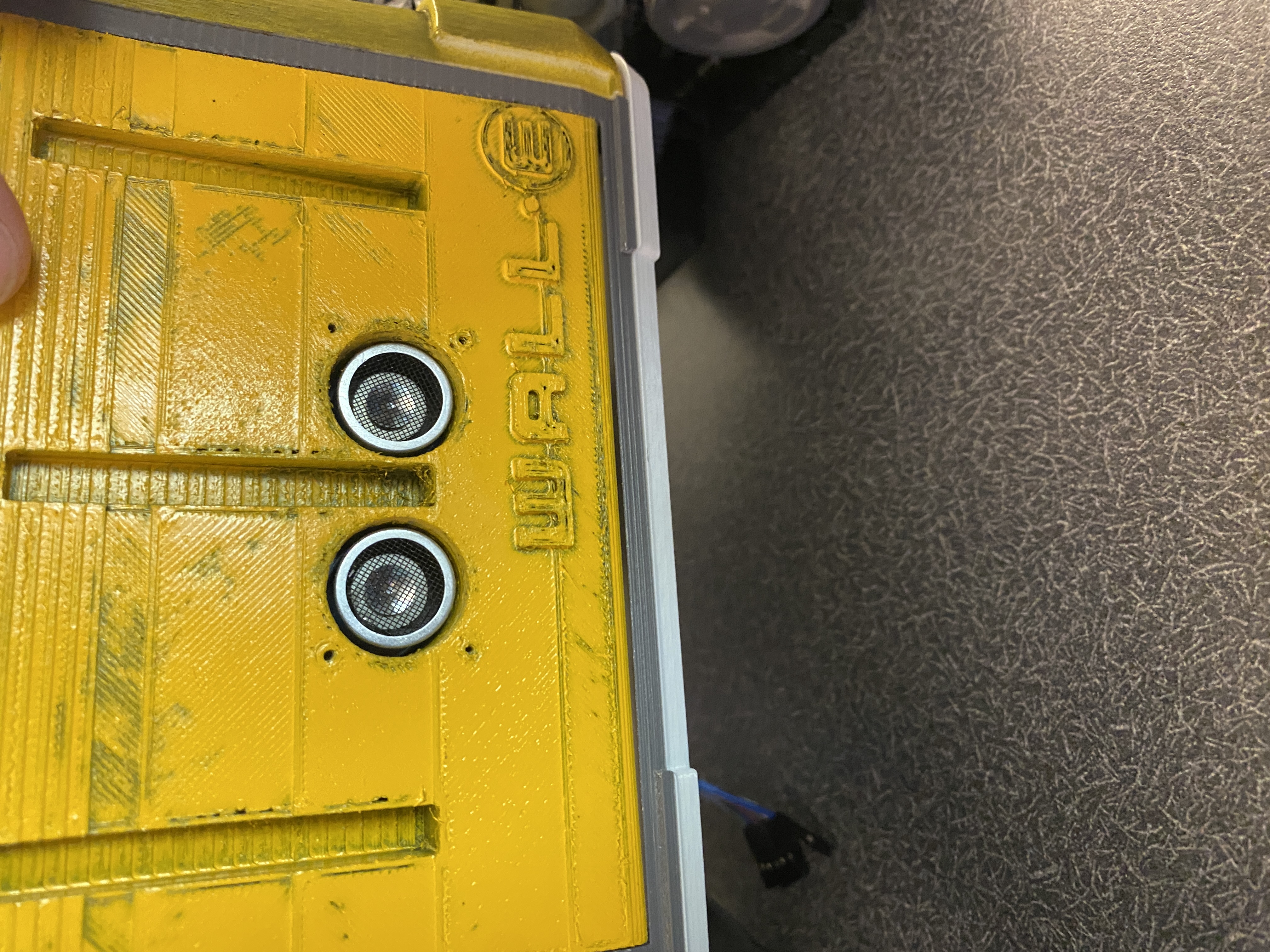
WALL-E HCSR04 Placement
- The Ultrasonic sensor is located within the front panel of WALL-E To learn more about the design visit the Mechanical Design page.
Motors
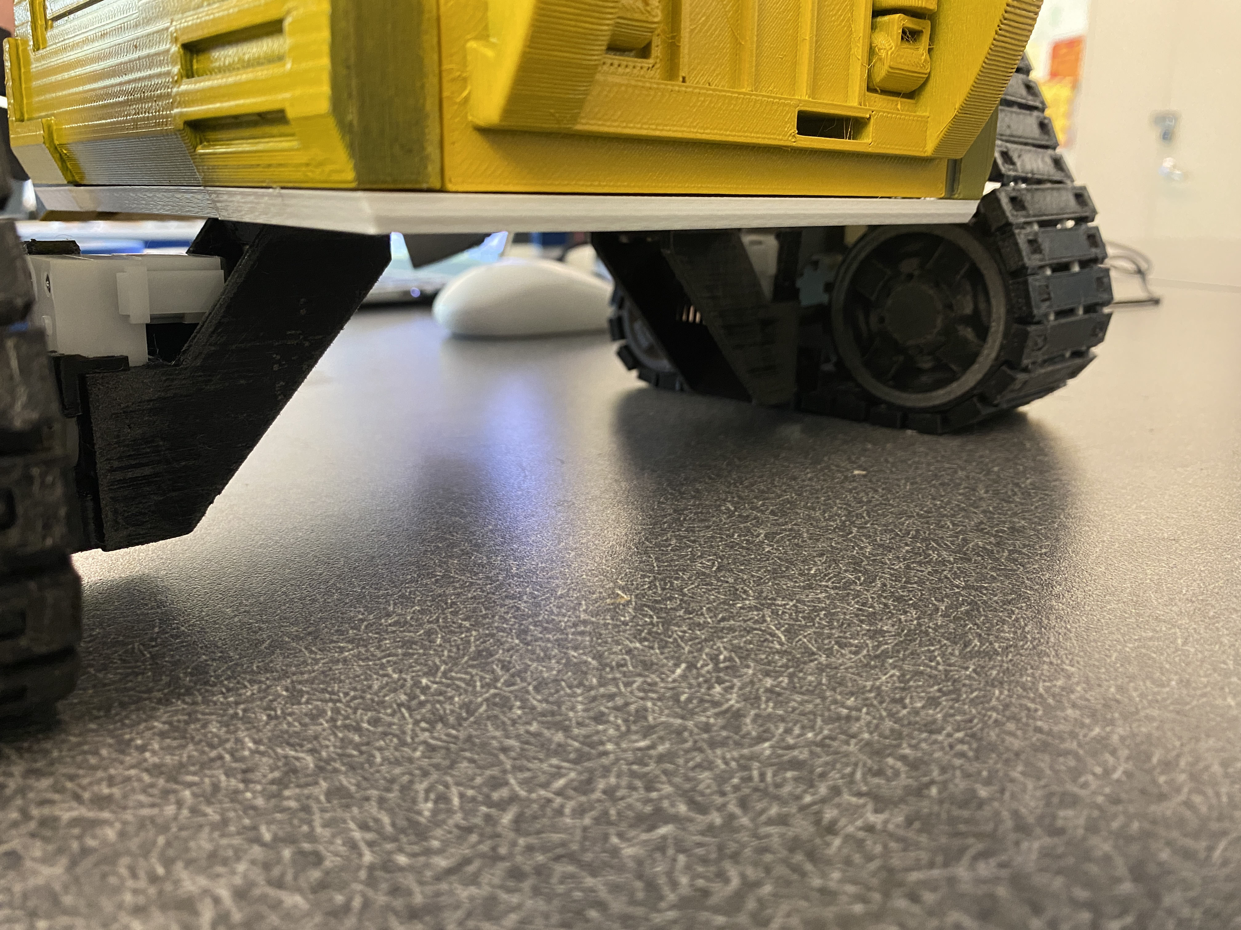
WALL-E Motor Placement
- The motors where placed directly underneath the bottom panel on a custom mount which you can learn more in depth at the Mechanical Design page.
Servos
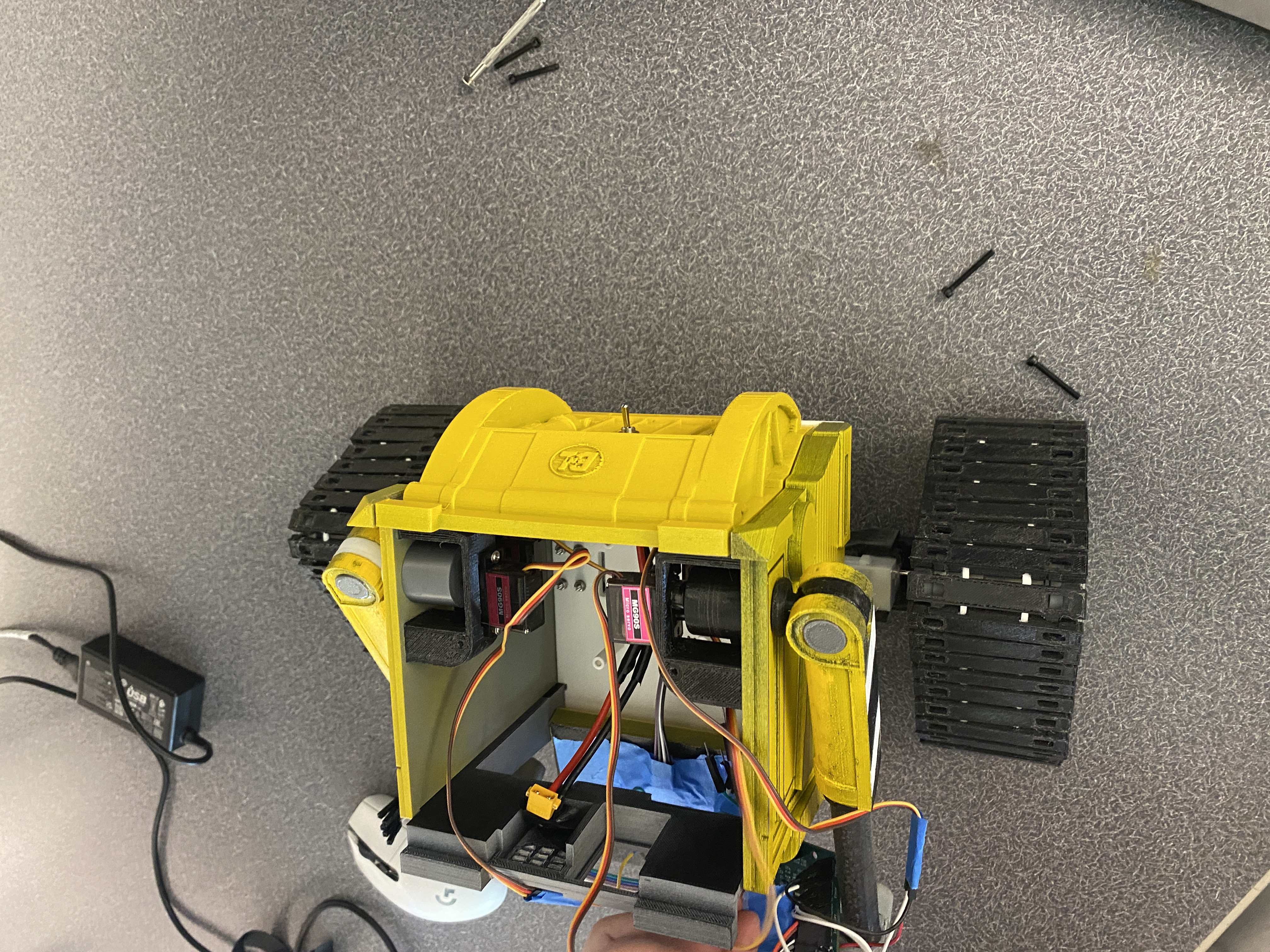
WALL-E Servo Placement
- The servos are placed closely near the arm area on the side panels of the WALL-E body.