Overview
This page will explain the Mechanical Design aspects of the WALL-E project. Starting with mechanical design ideas and phases and the original CAD Model of WALL-E. 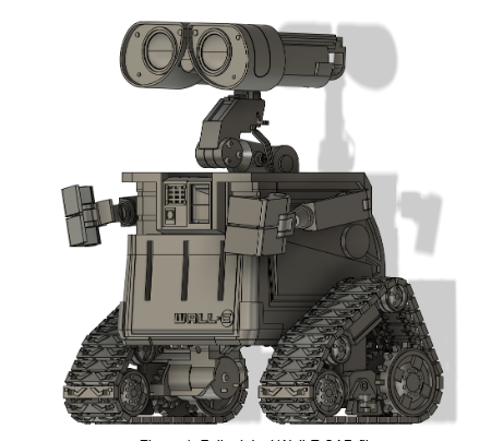
Where it all began!
The basis for the mechanical design for this project is CAD project created by S. Bluett. His model is very screen accurate and is designed so that the arms and treads can actually move. His design also includes the ability to mount servos in the head to control head movement but those were omitted for this project. Even though we were able to use most of the model, there were many components that had to be modified for our purposes. The following is a list of all the components that were changed and a brief description of each change:
List of modified Wall-E components:
- Right eye: Modified so that the eye cap was removable and added camera mounts
- Front panel: Added mourning holes and sensor holes for the ultrasonic sensor
- Back panel: Added hole and slot for on switch and channel for STLink cables
- Side panels: Added servo mounting locations for hand servos
- Bottom Panel: Added mounting locations for Motherboard and IMU and routing for motor cables
- Arm Servo Mounts: Increased servo distance from side panel to accommodate arm strings
- Inner Arm Hinge: Increased thickness, added center channel and rotational cutout for string routing
- Outer Arm Hinge: added center channel and slot for sting routing
- Arm Hinge Pin: broke into 2 pieces and added string routing channel
- Arm Barrel: added string channel and rubber band hook
- Arm piston: Increased length to reach objects in front of Wall-E and added string channel
- Hand Hinge Pin: added sting mounting hole
- Finger: added rubber band mounting point
- Motor mounts: completely redesigned to accommodate different motors and mount to the new bottom panel
- Motor axle: modified to interface between the new motors and tread gear
- Tread plates: modified to remove grip for ease of printing
- Top Panel: added hole for E-Stop (unused in final design)
Modified Components
Head Modifications
Right Eye
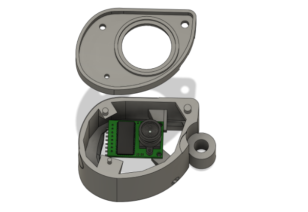
Starting with the Right Eye, the original model was hollow and didn’t have any camera mounting options. In order to accommodate the camera and allow for easy access, the front panel was sliced so it was removable and mounting points for the camera module and front panel were added. The front panel mounting points were aligned so they would match the faux screw bumps on the original model
Body Modifications
Body Front Door
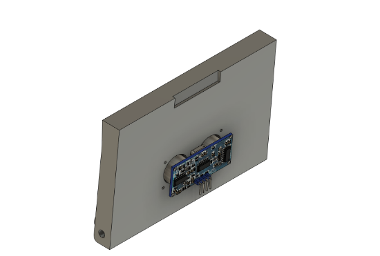
The next major area that had to be modified was the body. In order to accommodate the ultrasonic sensor, the front door panel was given cutouts for the transducers and mounting holes were added for the board.
Bottom Panel
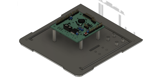
In the original design, there were no mounting structures for any electronics. All of the electronics were simply shoved in the body. For this project we wanted to address that issue. In order to mount the main board, 4 tall standoffs were used. The standoffs were made tall so that wires could be routed under the board. Additionally, a similar mount for the IMU was made but it was only made tall enough to route its own wires underneath. Finally, larger slots were added to accommodate the 6 pin cable harness that each motor/encoder combo needs.
Back Panel
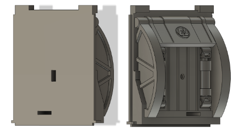
The back panel had 2 minor alterations. First, a slot was created to route cabling for the STLink and UART connectors so that Wall-E could be programmed with the main board inside. Secondly, the on switch for the Wall-E was placed in the rear so it needed a hole and a partial slot for the switch housing. The switch was carefully measured with calipers and then the hole was made slightly bigger to account for tolerance issues.
Side Body Panels
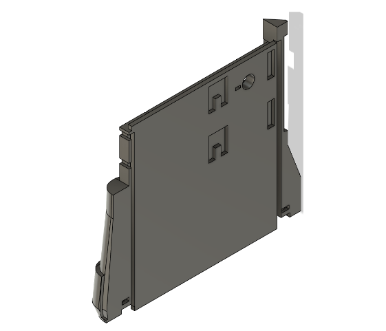
The final modifications to the body were adding mounting for the hand servo brackets below the mounting for the arm servos. Since the hands were too small to accommodate full servos, we decided to place the servos inside the body and then run a pulley system through the arms to actuate the hands. The string runs into the arm joint and then gets routed down to the servo that actuates it.
Servo Mounts
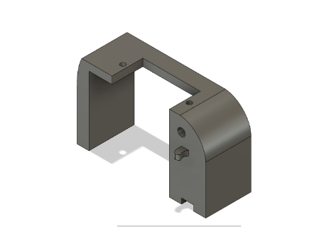
In the original design, there was no accommodation for the hand pulley system so the arm servo bracket was designed to mount the servo right up against the body. To allow for the string to pass through the inner arm hinge without compromising the structural integrity of the hinge, the servos had to be moved further into the body. To accomplish this, the arm servo mounting brackets were elongated
Arm modifications
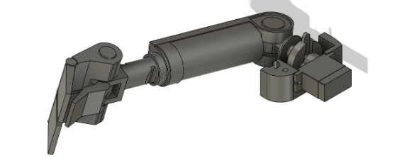
Before diving into the specific parts of the arm that were modified, the full arm system will be explained. The key design parameter that we worked towards was the ability of the arm to actuate without disturbing the pulley system and unintentionally actuating the hands. This proved to be a major challenge and required multiple design iterations. At first, I thought that the string could be routed out the side of the arm and then a curved slot in the body would allow it to rotate with the arms. However, this design failed because the string was terminated at a fixed point inside the body so any movement relative to the body would tug on the string. Ultimately, we realized that the string had to be routed directly along the axis of rotation or else it would move relative to the body. Figure 8 shows the full arm assembly.
Inner and Outer Hinges
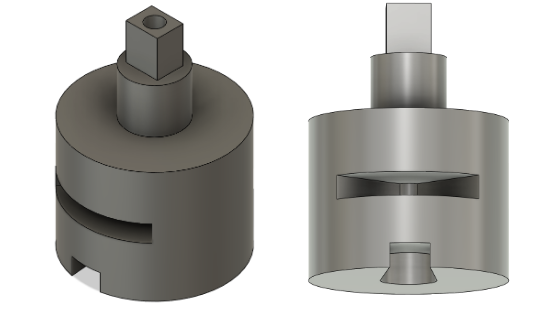
The 2 main components that were modified and iterated upon were the inner and outer hinges that interface with the servo, body, and rest of the arm. As stated earlier, the arm servos were moved further into the chassis to accommodate the string. This meant that the arm’s inner hinge also had to be elongated. In order for the sting to be able to pass through the axis of rotation and then exit straight down, a circular slot was cut out from this piece. This allows the arm to rotate a full 90 degrees without impeding the pulley system. We decided that 90 degrees would be enough rotation for full arm range of motion while also not compromising the integrity of this piece. 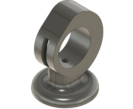
The outer hinge piece interfaces with this piece and the rest of the arm so it must have routing the string. Figure 10 shows this piece. We decided to make a slot for the string on the arm interface side so that the angle of attachment would have some tolerance. If we just used the same size hole, the string could very easily get pinched and no longer operate correctly.
Arm Barrel and Axle
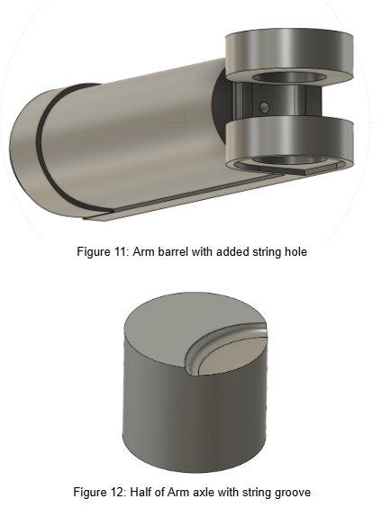
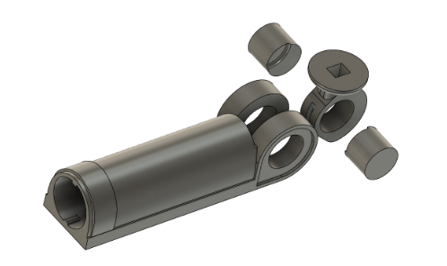
The outer arm hinge needs to connect to the arm barrel shown in Figure 11 via an axle. However, the axle would get in the way of the string so a groove was placed in the axle to route the string. This part needed multiple revisions because we realised after printing it that it was actually impossible to route the string since the outer hinge, axle, and barrel all had to be aligned while feeding the string around the corner. This issue was solved by breaking the axle into 2 sections that could be fed into the barrel/hinge hole from either side once the string was routed through those components. Figure 12 shows the final design of one half of the hinge.
Arm Piston
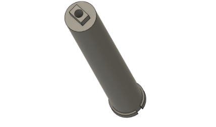
The final modified piece of the arm assembly is the arm piston. It needed to be significantly longer than the original for the hands to reach out far enough to pick up a box. Additionally, a channel was made down the center for the string.
Hand Modifications
Hand Axle
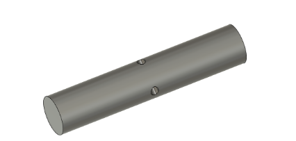
The modifications to the hand were fairly minimal. Firstly, the hand axle was modified to have a hole through it to tie the string to. The one important note is that the string was tied off to this hole and then wound around the axle once so that the lever arm would be the full radius of the axle rather than the distance from the center to the hole.
Finger and Arm Barrel Hook
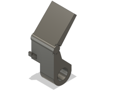
Finally, the hand had to be modified so that a rubber band could provide backwards tension, keeping the hand open when not actuated by the servo. This was accomplished by creating a small hook on the outside of one of the fingers. The other side of the rubber band secured to a hook created in the arm barrel
Arm Barrel Hook
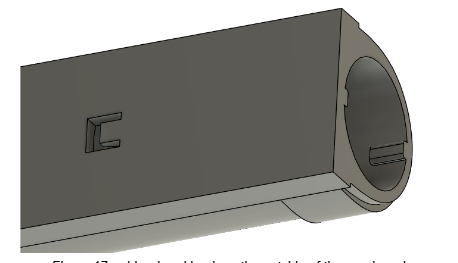
Finally, the hand had to be modified so that a rubber band could provide backwards tension, keeping the hand open when not actuated by the servo. This was accomplished by creating a small hook on the outside of one of the fingers. The other side of the rubber band secured to a hook created in the arm barrel
Wheel and Drive Modifications
Moving on from the arm and hand design, the motor mount design was arguably the most time consuming and complex part to make since it was made completely from scratch.
Motor Mount
The challenge of designing this part was that it had to interface with the holes on the bottom of the body, secure and align the motor while also allowing the motor to be removable and the wires accessible, and finally interfacing with the tread frame. If the alignment problems weren’t enough, this is also the part that supports the entire weight of the robot so it had to be strong and rigid. 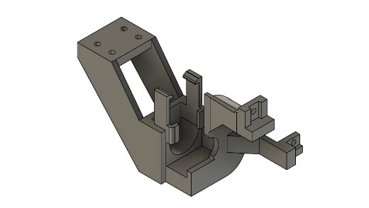
The main reason this part had to be designed from scratch was that the original model used different motors that didn’t have encoders. For this design, we wanted full feedback control of the motors so we chose to use the Romi motors from Pollolu. The slot for mounting these motors was inspired by the design of the motor mounts on the Romi chassis, having flexible clips to secure the square side of the motor and guides to hold the motor tightly. The design of this section alone underwent multiple revisions to get the tolerances for 3D printing just right. The final design was snug yet easily removable. The tread frame interface was inspired by the original model’’s motor mount system. It has two arms that press fit into the frame and then are secured with screws. Finally, the back section that connects to the main body was designed with enough room for the motor electronics to slide in the back. Additionally, it was aligned to the holes in the bottom and its 2 arm design allows for minimal flexing.
Motor Tread Gear Shaft
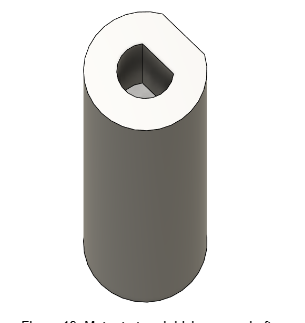
In the original design, the tread driving gear was designed according to the axle dimensions of the original motor. To interface with this gear, a new axle had to be designed with the profile of the Romi motor axle on the inside and the profile of the driving gear on the outside. Since the Romi motor axle is so small, the inner dimensions had to be iterated a few times to get a perfect tight press fit. At first it turned out too small so we couldn’t get it on the axle, then it was too big so it would slip, then finally we perfected it based on the properties of the specific 3D printer used.
Tread Plates
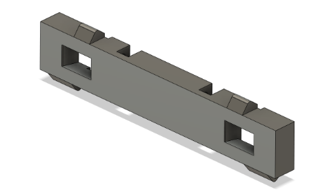
The final part that was modified was the tread plate. In the original design, the tread had bumps to give them more tractions. However, this meant that there was no good surface to print them on. The full design required 70 of these to be printed so if we used support material, it would be a lot of work to remove from all of the small components. We decided to remove the bumps and print the treads on their bottom face for this reason. In addition to the removal of the bumps, the locking notches were extended to the build plate so they wouldn’t have overhangs. This didn’t interfere with the functionality of the treads, it only made them easier to print. We still had to add a little support material to the grooves on the inside but this was much faster to remove.
Revised but Not Included in Design
Top Body Panel
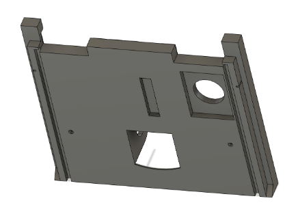
The only modified part that was not included in the final design was the mount for the emergency stop in the top panel of the body. The original idea was to have a large emergency stop button on the top of Wall-E so that we could completely cut power in case of major failure. We ultimately decided against this plan for multiple reasons. Firstly, we already have the off switch on the back which does the exact same thing and is easily accessible. Secondly, the giant E-Stop sticking out of the top of Wal-E would have detracted from the aesthetic of the robot. Finally, when trying to print the part with the hole, it failed twice in a row on 2 different printers and we didn’t have time to try a third time so we decided to skip it
WALL-E Print Information and Paint Job
After all the parts were designed, they were 3D printed on various printers. The first prototypes were printed in Cal Poly’s Innovation Sandbox. This is a free service for students to get their parts printed on campus. It is super easy because all you have to do is upload your STL files and they will do all the slicing and printing for you. However, later in the quarter, the Innovation Sandbox stopped responding and many of the parts we requested to be printed were never delivered. This led us to explore other options. We ended up using a combination of a personal printer and the printers in Cal Poly’s Mustang 60 shop. 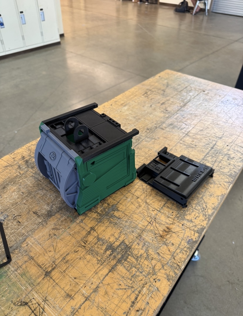
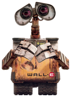
Once the parts were printed, they were sanded and painted with the colors of Wall-E from the movies. We took inspirations from these photos: 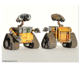
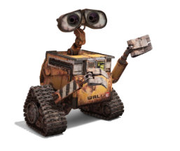
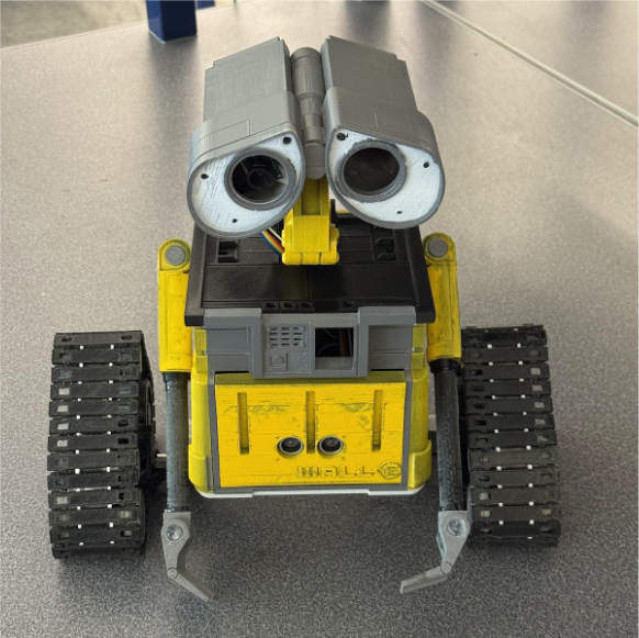
In order to achieve the weathered look of Wall-E, all yellow parts were first painted black, then a single coat of yellow was applied, this allowed some of the layer lines with black paint to peek through and give the parts Wall-E’s signature dirty look. For some of the finer details, like the arms and eyes, sections were taped off and painted in layers. This process gave sharp lines which didn’t fit weather vibes so the lines were roughly sanded to bleed the colors a bit. Finally, for all of the exposed metal parts, we didn’t use metallic paint because that would look too shiny. Instead, these parts were painted white first and then a single layer of grey paint was applied to purposely leave some white exposed underneath. This gave the parts a highlighted look while leaving them matte, emulating the weathered metal scene in the movie.